Connecting the vehicle
to the digital platform
Architecture, integration and data transmission.
How the ME Systems device works
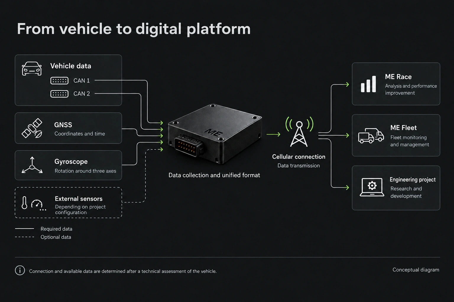
- Step 01
Integration
Two independent CAN interfaces. The connection method is tailored to each vehicle.
- Step 02
Signal acquisition
Vehicle parameters are enriched with GNSS coordinates and gyroscope measurements.
- Step 03
Unified format
Signals from different sources are standardised for further analysis.
- Step 04
Gear
Data is transmitted over a cellular connection to ME Race, ME Fleet or a custom engineering project.
Connecting the vehicle to the digital platform
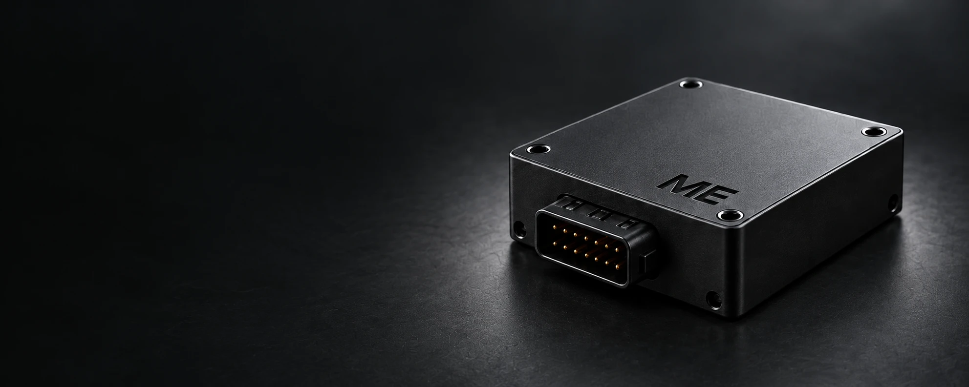
Vehicle Data is the ME Systems hardware and software layer connecting a real vehicle to the platform’s digital products. It is more than a tracker and is not a standalone mass-market product.
Its role is to acquire the required vehicle data, enrich it with navigation and inertial measurements, standardise it and transmit it to ME Race, ME Fleet or a custom engineering project.
Integration tailored to each vehicle
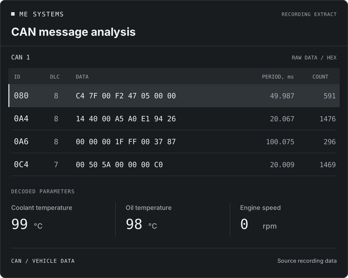
The system is configured for the requirements of each vehicle. Two independent onboard CAN interfaces allow the platform to work with different data buses simultaneously.
For example, key motion and powertrain parameters may be read from Powertrain CAN, while system self-diagnostic statuses may be read from Diagnostic CAN. If the required data is in a FlexRay cluster and adding another node is impractical, integration can use the diagnostic CAN bus or DoIP.
The connection method, available data and compatibility are determined after a technical assessment of the vehicle and use case.
Navigation and inertial measurements
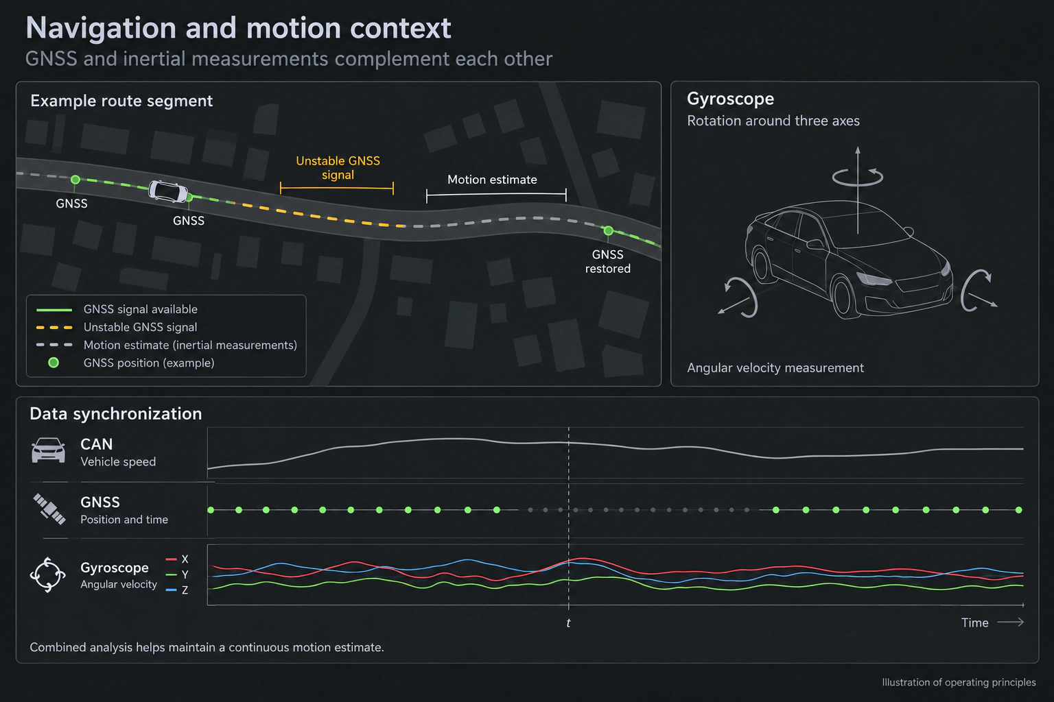
Vehicle Data also includes a navigation module and a three-axis gyroscope. The navigation module associates data with location and time, while inertial measurements provide further insight into vehicle motion.
When the GNSS signal is unstable, inertial measurements supplement positioning data and help maintain continuous motion estimates. Analysing these sources together can help distinguish a suspension impact from a pothole from an event that may indicate a collision.
Events and fallback alerts
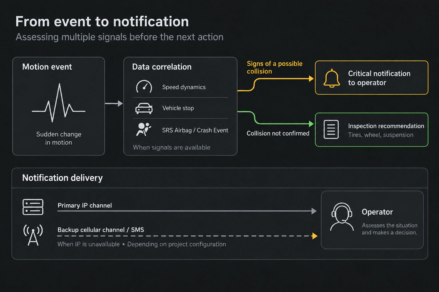
If a sudden acceleration is corroborated by deceleration, a stop, the SRS Airbag indicator or a message Crash Event on the CAN bus, the system can generate a critical alert for the operator. If the primary IP connection is unavailable, the message can be sent through a fallback cellular M2M channel or by SMS via an SMPP gateway.
An emergency services notification workflow can be included where required. If signs of a collision are not confirmed, the AI assistant may recommend checking the tyres, wheel rim and suspension.
Connectivity and additional sensors
The module includes cellular connectivity supporting 2G, 3G and 4G. It transmits data over an available internet connection and supports a configured fallback communication method if that connection degrades or becomes unavailable.
External analogue sensors can be added where needed using the device’s ADC/DAC channels. This brings native vehicle data, CAN, DoIP, GNSS, gyroscope measurements and additional sensor data into a single stream.
This architecture makes Vehicle Data a flexible engineering foundation for different vehicle types. Compatibility still requires a prior technical assessment.